Frequency synthesizer module


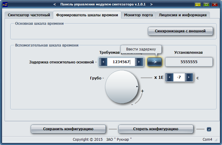
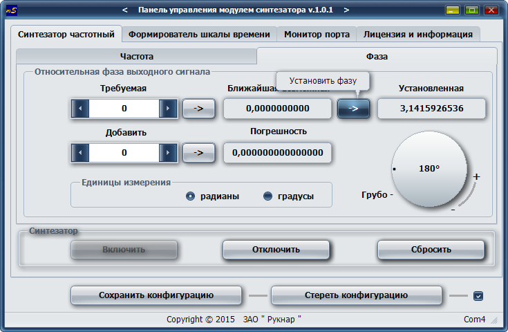
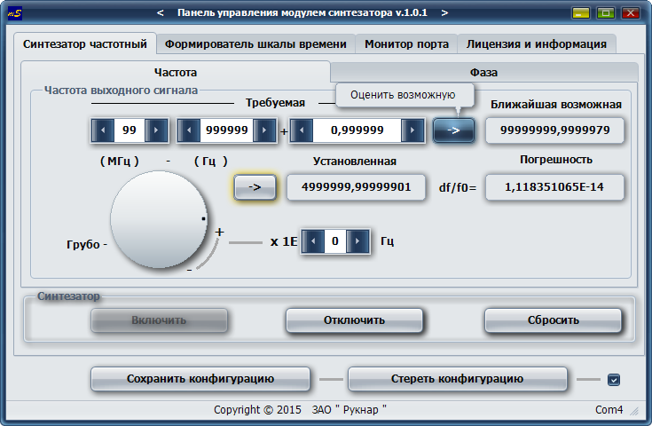
 The frequency synthesizer module is a multifunctional device intended to prevent incompatibility problems between different models of frequency standards from different manufacturers and different generations and to provide a complete set of outputs with the standard signals in one device. Manufactured as a module, this device can be installed in any modular instrument of JSC RUKNAR and can significantly expand its functionality. The device has three independent functional blocks in one module: frequency synthesizer, standard signals former and time scale former. Optionally, any of these blocks can be excluded from the device. The module has external control via USB 2.0 interface from a PC or tablet PC. Software included.


Table 1. Available options of the sintesizer module.


Block

Option

00

-01

-02

-03

1. Frequency sintesizer

-

2. Dual channel time scale former

-

3. Standard signals former

-


Table 2. Specification of sintesizer module.

No

Parameter

Unit

Value

guaranteed

typical

Dual channel time scale former

1.

Period

s

1

1

2.

Number of outputs / type of connector


2 / SMA


3.

Pulse amplitude @ 50 Ohm load

V

не менее 2.5

2.6

4.

Pulse width

us

10 … 20

12.8

5.

Rise time

ns

not more than 5

2

6.

Fall time

ns

not more than 5

2

7.

Programmed delay between base and additional time scales in the range

us

0…999999.9

0…999999.9

8.

Delay programming step

us

0.1

0.1

9.

Synchronization error of the base time scale on the external time scale

ns

100


10.

The ability to continuously smoothly change the delay

there is


11.

The ability to save delay in memory and restore it on power-on

there is


Standard signals former

1.

The frequencies of the output signals

MHz

1, 5, 10


2.

Number of outputs / type of connector


3 / SMA


3.

Signals form


sine


4.

The effective value of the output voltage at the 50 Ohm load

V

0.8 … 1.2

1.0

5.

Second harmonics level

дБ

-30

-35

Frequency sintesizer

1.

Signals form


sinusoidal + pulse


2.

Number of outputs / type of connectors


2 / SMA


3.

Output frequency programming range

Hz

100 …100 000 000


4.

Output relative phase programming range

degree

0 … 360


5.

Phase programming step

degree

< 0.03

0.022

6.

Frequency programming step

Hz

< 4.10-6


7.

Second harmonic level for sinusoidal signal

dB

-30

-40

8.

The effective value of the output voltage @ 50 Ohm load for sinusoidal signal

V

0.8 … 1.2

1.0

9.

Pulse amplitude @ 50 Ohm for pulse signal

V

not more than 2.5

2.6

10.

Rise and fall width

nc

not more than 2

1,7

11.

Pulse duty cycle


0.45 … 0.55

0.48

12.

Added instability at synthesis a sinusoidal signal


< 2.0.10-12

13.

The ability to directly set the frequency and phase of the output signal with a specified accuracy.

there is


14.

The ability to continuously smoothly change the phase and frequency of output signal

there is


15.

The ability to save phase and frequency in memory and restore it on power-on

there is


Do you have questions or don’t know what to do? Leave a request, we will call you back
* - required fields